Basic operation of the junction
"Attachment Point" function is used to define junction points against shapes, parts, assemblies, etc. and to connect them with other objects.
Insert "Attachment Point"
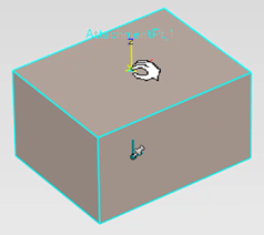
Select the parts and click "Attachment Point" on the Tools tab.
If you click on any point on the object, the Attachment Point will be inserted.
If you click on any point on the object, the Attachment Point will be inserted.
Attachment Point Name and Operation Settings
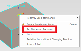
After inserting an Attachment Point, place the mouse over an Attachment Point and the mouse icon will change "Hand" mark.

If it does not change, right-click on the Scene and open [Show].
Confirm and Uncheck "Hide Attachment Points on Selection"
In this state, you can right-click and open "Set Name and Behaviors" to set.
Enter "User Name" and specify "Male(_M)", "Female(_F)", or "No Paired".
The username you entered in the name frame + [ _M/F/N ] is displayed.
There are some types of [No Paired] and [Default(~)], and no pair can be used in the left drag drop.
Default is the setting of which junction to default for multiple males, females, and neutrality.
If the default is specified, the default takes precedence in the left track drop.
Also, if the “Coincident(CnP)” constraint is enabled, the part will follow the TriBall's movement even if the join point is changed using the “Attachment Point Connector”.
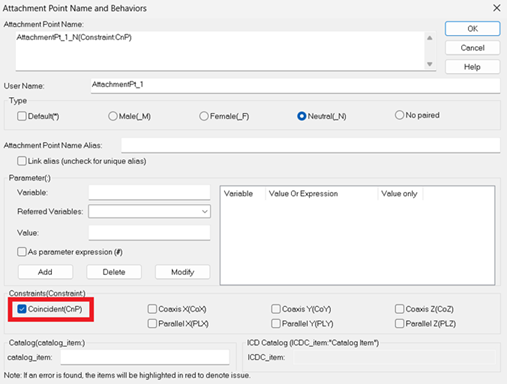
Please refer to the below.

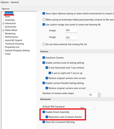
The following options must be set in order to use "Attachment Point" function.
Open 3D Options.
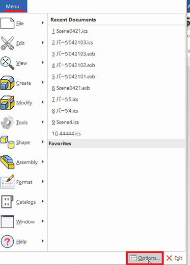
Then check “Enable Smart Assemby” of "Advanced" on the "General" group.
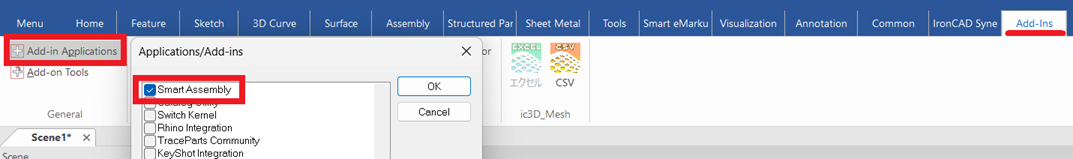
[Go to the “Add-ins” tab, then “Add-in Applications” and enable “Smart Assembly”.
Related Articles
Set robot restraint with standard functions
You can use IRONCAD’s standard [Position Constraints] feature to apply basic motion to robot data. Example: Vertical Articulated Robot (6-Axis) In addition to vertical articulated robots, you can also simulate the motion of horizontal articulated ...Mechanism Mode - Drug operation
The [Mechanism Mode] is a feature that allows for simplified verification of 3D motion. There are four types of drag operations available in Mechanism Mode: Standard Rigid Localized Relaxation Each mode differs in how motion is transmitted. ...Reverse Expansion Operation
In icVault, you can open the detailed view of a registered file from the file list and perform Expansion/Reverse Expansion to check which data the file is associated with. This section explains the procedure for performing Reverse Expansion from the ...Value is not displayed during movement operation by TriBall
IRONCAD moves primarily using TriBall. You can move the data by using TriBall outside handle with Left mouse click. After moving, you will usually see the moved value and change the value with keyboard input. Show/hide display can be set by TriBall ...Create a model with Sheet Metal Stock and Bend
This section explains the basic operations for creating a model using [Stock] and [Bend] from the sheet metal catalog. Procedure: [1] Drop [Stock] and select material. [2] Drop [Bend] into the stock part, then modify shape (angle, length or wide size ...