Applying an Image to a Surface
This section explains how to import and visually display an image on a specific face of a solid or surface in IRONCAD.
Use case
- Knurling
- Bolt threads
- Serration patterns

While these features can be physically modeled, doing so significantly increases both modeling time and data size, which may slow down IRONCAD’s performance.
This method—applying a texture image—is one way to maintain smooth operation in IRONCAD.
When fine geometry is not required, using an image to represent the part (as shown in the examples above) is recommended to reduce data size and optimize performance.
Steps (Example: Diamond Knurling Image)
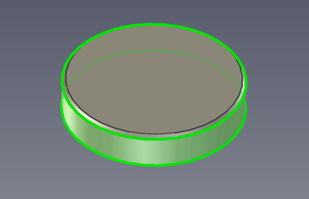
[1] Slowly click several times on the face of the part until it turns green.
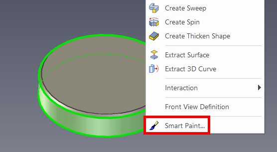
[2] Right-click the green face and select [SmartPaint] from the context menu.
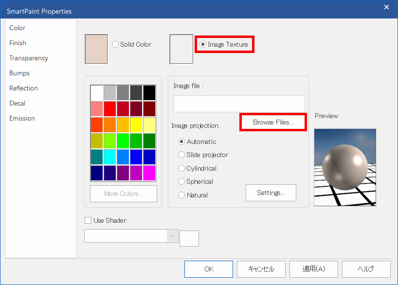
[3] Check the [Image Texture] option, then click [Browse Files].
[4] Select your image file. ※Please prepare the image in advance (e.g., via screenshot or download).
[5] Set the "Image projection" type to [Cylindrical].
[6] Within the "Cylindrical Mapping" section, click [Settings],
then adjust the [Horiz ratio:] and [Height:]. Click [OK] to confirm.
then adjust the [Horiz ratio:] and [Height:]. Click [OK] to confirm.
[7] Click [OK] on the SmartPaint dialog to finish.
The diamond knurling image is not included by default in IRONCAD.
Please obtain it separately, such as from the internet.
The Cylindrical mapping values should be adjusted based on how the image appears on your part. Fine-tuning may be necessary for optimal display.
Please refer to the video below.
IC-102
IC-102
Related Articles
Get an image in Rendering Now
This section explains how to use the [Render Now] function. It allows you to display the current 3D view in a separate window and save it as an image. If the image quality is not satisfactory, please use: [Menu] → [File] → [Export] → [Export Image] ...Creating a Surface Texture Symbol
This section explains how to create a surface texture symbol in a drawing using CAXA Draft. The surface texture symbol is used to indicate surface roughness, typically on reference planes or mounting surfaces such as brackets. CAXA Draft supports ...Applying Colors with SmartPaint
[SmartPaint] feature is a feature that allows you to apply colors to parts and faces. Memo: In addition to enhancing the visual appearance to resemble the final product, SmartPaint can also be used to prevent editing errors. For example, by assigning ...Projecting a Surface
This section explains how to project a surface part in CAXA Draft. In the [Scene] browser, a surface is represented by a yellow icon (see “Part 2” in the figure below). To project a surface, you must first enable the option to include surfaces in the ...[Surface Finish] Scale Adjustment
This section explains how to change the scale (size) of Surface Finish. To change the scale of the entire drawing [1] Click [Surface Finish] style in the [Annotation] tab. [2] Change the value of [Scale:]. To change the scale of part of the drawing ...