Set Insert Joint Point and create continuous pipes and mounts
This section explains how to use the [Attachment Point] function to build continuous pipe structures or equipment base frames in IRONCAD.
In piping design and equipment base structures, it is common to use multiple sections of the same type of round pipes or square pipes.
To assemble these parts, you typically use the TriBall tool. However, when connection points are predetermined, adding Connectors allows you to place parts semi-automatically at the correct locations.
Procedure:
[1] Select element what you want to set [Attachment Point].
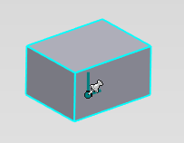
[2] Click [Attachment Point]
[3] Click arbitrary point.
[4] Move the cursor over the attachment point and right-click when it turns yellow.
Then click [Set Name and Behaviors].
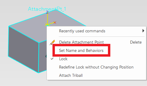
Then click [Set Name and Behaviors].
[5] Enter [User Name] and select [Type].
You can connect with other users with the same username.
[Type] can be connected Male x Female or Neutral x Neutral.
Each connector contains a long axis and a short axis:
- The long axes are facing each other.
- The short axes point in the same direction.
When two parts with configured connectors are brought together, they will automatically align and attach according to the connector settings, enabling efficient assembly of continuous piping or frame structures.
How to connect:
- Register in the catalog and drag & drop from the catalog
- [Connect using the Attachment Point Connector
Please refer to the video below.
IC-073
Related Articles
Creating a Block (CAXA Draft)
This section explains how to create Block parts in CAXA Draft. Block parts allow you to register frequently used lines or shapes as blocks so that they can be easily inserted into drawings. By registering items such as bolts, pins, and annotations as ...Create tape dimensions/curvature radius dimensions/large diameter circular dimensions/continuous angle dimensions
The CAXA Draft drawing explains how to create the following special dimensions: Pyramid/Pitch Curvature Dimension Big Arc Angle Continuous Please refer to the video below. CA-033Creating Piping with [Auto Route]
Starting with IRONCAD 2025, a new [Piping] tab has been added, providing piping creation functionality. This section explains how to create piping from a flange using [Auto Route] under the [Piping] tab. Procedure: [1] Go to the [Piping] tab and ...Moving a View from an Arbitrary Base Point by Stretch
This section explains how to move a projected view from any chosen base point in CAXA Draft. Procedure: [1] On the Drawing tab, click [Stretch]. [2] In the Instance Menu at the lower-left of the screen, set Item 1 to [Select by window] and Item 2 ...Create continuous angle dimensions
This section explains how to create [Angle Continuous] dimensions. As shown in the figure below, you can create dimensions for a series of continuous angles in a single operation on a plan view or similar drawing. Please refer to the video below. ...