Create Broken View
Procedures:
[1] Click "Broken View" and select the projection view you want to create.
[2] Select the type from item 1 of the status bar.
zigzag/curve/line
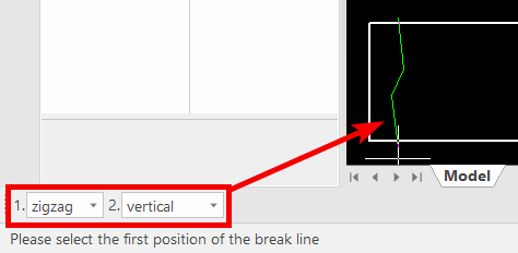
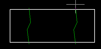
[3] Specify on two ranges to omit (start and end). ※Several can be created
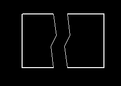
[4] Right-click to complete.
[2] Select the type from item 1 of the status bar.
zigzag/curve/line
[3] Specify on two ranges to omit (start and end). ※Several can be created
[4] Right-click to complete.
If you want other projections to be in the same position
[5] Click [Projection View] on the [3D Interface] tab.
[6] Select [Sync Broken View] from item 2 of the status bar.
[7] When select the view created in [4], added Projection View.
--------------------------------------------------------------------------------------------------------------------
If you want to create Broken View in the same position for multiple already projected views.

It is not possible to create an abbreviated drawing at the same location on an already projected front view or plan view only with the command.

There are ways to create a reference (cylindrical hole or block hole, or cylindrical or block) in the position you want to create Broken Views on the 3D data side and select based on it, but please refer to it as we may add unnecessary shapes.
If you have a shape that already becomes the standard in the position you want to omit, use it.
Procedures:
[1] In addition to the Primary View and Top View, add with new Primary View or Top View outside the frame.
[2] Make the shape added on the 3D side recognizable.(shadowline display, etc.)
[3] In creating Broken View select the endpoint (or center of the intersection or circle) of the reference shape of the projection view that adds the position of the line to be omitted.
[4] After creating Broken View, delete the added projection and the reference shape on the 3D side.
Please refer to the video below.
CA-007
Related Articles
Editing Centerlines After Creating a Broken View
This section explains how to edit centerlines after creating a broken view in CAXA Draft. Procedure: [1] Select the broken view, right-click, and click [View edit]. After creating a breakout view, you cannot edit the centerline by double-clicking the ...Create a detailed diagram
This section explains how to create a [Detail View] by enlarging a specific area of a projection drawing in CAXA Draft. A detail view improves the clarity of drawing information by enlarging areas where lines overlap and make dimensioning difficult, ...Create Dimensions on an Isometric View
This section explains how to create dimensions on an isometric view exported from a 3D scene. If the Isometric View Has Not Yet Been Created In the following steps, make settings and create dimensions: [1] Open CAXA Draft, then go to [Menu] → ...Create Hatching in a Projected View
This section explains how to create manual Hatching in a projected view that is linked to a 3D drawing, independent of Section View. Procedure: [1] Right-click on the projected view and select [View Edit] or [View Edit In-place] to enter the ...Select the Front View definition in Scene
You can pre-set the front view definition to the 3D Scene when projecting on CAXA Draft and 2D drawing. Explain how to define a front view. Right-click Parts/Assembly and click Define Front View in 3D. Valid settings for CAXA Draft and 2D Drawing ...