Set robot restraint with standard functions
You can use IRONCAD’s standard [Position Constraints] feature to apply basic motion to robot data.
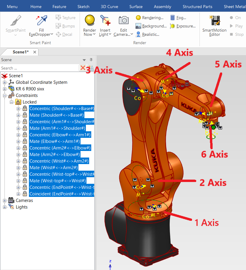
Example: Vertical Articulated Robot (6-Axis)
In addition to vertical articulated robots, you can also simulate the motion of horizontal articulated robots (SCARA) and robots with special link mechanisms using [Position Constraints] and Mechanism Mode.
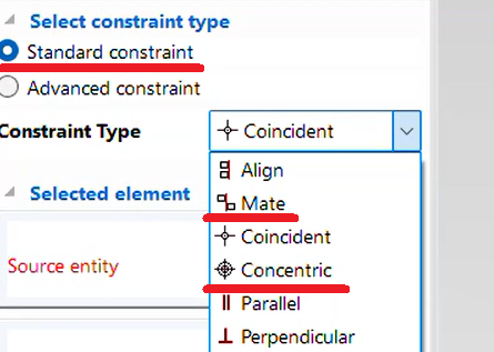
In IRONCAD, apply [Concentric] and [Mate] constraints between each axis.
Please refer to the video below.
IC-063
Related Articles
Set Parts as Active
When setting a part as active means currently modeled part only editable. This prevents accidental modifications to other parts. How to: Select the part you want to activate, then right-click and choose [Set as active] from the context menu. The name ...Alie cylindrical parts with concentric restraint
This section explains how to position cylindrical parts and cylindrical holes with different orientations using concentric alignment. Methods: Using TriBall to manually align parts concentrically → No constraint applied Using the [Concentric] ...Change the standard for 2D drawings
Set-Standard (JIS, ANSI, GB) can be changed. It can also be changed if the standard applied to the template you create are wrong. When you change the standard, the tolerances and each symbol on the [Dimensions] tab will change. ※It applies from newly ...Mechanism Mode - Drug operation
The [Mechanism Mode] is a feature that allows for simplified verification of 3D motion. There are four types of drag operations available in Mechanism Mode: Standard Rigid Localized Relaxation Each mode differs in how motion is transmitted. ...Basic operation of the junction
"Attachment Point" function is used to define junction points against shapes, parts, assemblies, etc. and to connect them with other objects. Insert "Attachment Point" Select the parts and click "Attachment Point" on the Tools tab. If you click on ...