Creating Staggered Dimension
This section explains how to create [Staggered Dimension].
When dimension lines and text become crowded, you can place coordinate dimensions using leader lines with bends to specify their positions clearly.
There are two methods for creating stepped leader lines: automatic and manual. The steps for each method are explained below.
1. Creating Steps Automatically
[1] Click [Staggered Dimension] in the [Annotation] tab.
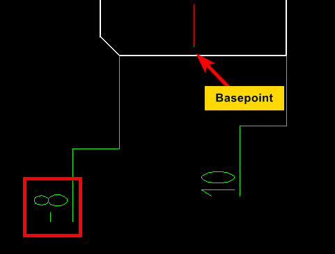
[2] Select the base point.
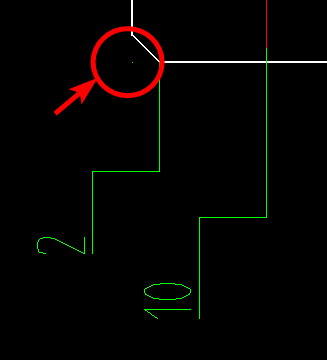
[3] Select the point to be measured.
The coordinate axis (X or Y) switches depending on the direction in which you move the mouse.
The coordinate axis (X or Y) switches depending on the direction in which you move the mouse.
[4] Place the dimension at the desired location.
When [Staggered Dimension] is selected, an instance menu appears in the lower-left corner of the screen.
(The menu items may be displayed in multiple rows in some images, but are shown in a single row in the actual interface.)
Description of the Instance Menu:
1. Sign/Positive sign
Rightward and upward from the base point are considered positive (+), while leftward and downward are negative (−).
If you want negative values to include the minus (−) sign, select [Sign].
If not, select [Positive sign].
2. Don't Draw Origin/Draw Origin
If set to Show, a dot is displayed at the base point, as shown in the figure.
3. Auto Break/Break Handcraft
Choose whether the leader line bend (step) is generated automatically or manually.
4. Break athwart/Bread in sequence ※In case Auto Break
Set the direction of the leader line.
5. L
Set the height of the leader line step.
6. H
Set the length of the leader line step.
7. Prefix
Any symbol or text entered here will appear before the dimension value.
8. Postfix
Any symbol or text entered here will appear after the dimension value.
9. Basic Value
If you wish to replace the measured value with a custom one, enter the desired value here.
By default, the [Calculated Value] is shown as the measured value.
Input is possible even during the dimensioning process.
The initial reference value is set to 0, but if you want to set a custom reference value for the second measured point, enter it before confirming the location of the second dimension.
2. Creating Steps Manuallyy
[1] Click [staggered Dimension] in the [Annotation] tab.
[2] Select the base point.
[3] SSelect the point to be measured.
The coordinate axis (X or Y) switches depending on the mouse movement direction.
[4] Specify the first bend point, second bend point, and the endpoint to place the dimension.
When [Derived Coordinate Dimension] is selected, the instance menu appears in the lower-left corner of the screen.
Description of the Instance Menu:
1. Sign/Positive sign
Rightward and upward from the base point are considered positive (+), while leftward and downward are negative (−).If you want negative values to include the minus (−) sign, select [Sign].If not, select [Positive sign].
Rightward and upward from the base point are considered positive (+), while leftward and downward are negative (−).
If you want negative values to include the minus (−) sign, select [Sign].
If not, select [Positive sign].
2. Don't Draw Origin/Draw Origin
If set to Show, a dot is displayed at the base point, as shown in the figure.
3. Auto Break/Break Handcraft
Choose whether the leader line bend (step) is generated automatically or manually.
4. Prefix
Any symbol or text entered here will appear before the dimension value.
5. Postfix
Any symbol or text entered here will appear after the dimension value.
6. Basic Value
If you wish to replace the measured value with a custom one, enter the desired value here.By default, the [Calculated Value] is shown as the measured value.Input is possible even during the dimensioning process.The initial reference value is set to 0, but if you want to set a custom reference value for the second measured point, enter it before confirming the location of the second dimension.
If you wish to replace the measured value with a custom one, enter the desired value here.
By default, the [Calculated Value] is shown as the measured value.
Input is possible even during the dimensioning process.
The initial reference value is set to 0, but if you want to set a custom reference value for the second measured point, enter it before confirming the location of the second dimension.
Related Articles
Creating a Half Dimension
This section explains how to create a half dimension. The value displayed in a half dimension is calculated as the distance between two specified points × 2. Procedure: [1] Click [Half Dim] in the [Annotation] tab. [2] First, select a midpoint or ...Creating an Angular Dimension Using [3-Point Angular Dimension]
One method for adding angular dimensions to geometry in CAXA Draft is using the [Three-point Angle]. This section explains how to create an angular dimension using this method. The [Three-point Angle] dimension allows you to define an angle by ...Create Progressive Dimensions (Coordinate Dimension)
In CAXA Draft, progressive dimension is referred to as [Coordinate Dimension]. To create dimensions based on any arbitrary reference point in the drawing, use [Align] in the [Coordinate Dimensions]. When you select [Align], the instance menu will ...Creating Quick Coordinate Dimensions
This section explains the Quick Coordinate Dimension feature. Procedure: [1] Click [Quick] under the [Coordinate Dimension] menu in the [Annotation] tab. [2] First, click the point to be defined as the origin (base point). [3] Click any point where ...Use virtual intersections when creating dimensions
This section explains how to create from virtual intersect point when creating dimensions. Procedure: [1] Click [Smart Dimension] in the [Annotation] tab. [2] Before specifying a point, press the [Space] key. Alternatively, hold down the [Shift] key ...