Create Movement Using [Walk] Feature
This section explains how to create a movement that simulates walk a building from the camera's point of view.
Two cameras are required: the main camera and a viewpoint camera (walkthrough camera).

When executing the animation, make sure the perspective camera setting is turned on.
Procedure:
[1] Delete all default cameras except for the [Isometric] view.
[2] Click [Insert Camera] in the [Visualization] tab, then add a new viewpoint camera at the starting position.
For creating Walk camera.
[3] Add an animation path and rotation movement to the viewpoint camera so it moves through the building.
[4] Add related motions (e.g., rotations) to objects like doors, in accordance with the viewpoint camera’s movement.
[5] In the [SmartMotion Editor], adjust the track's start time and duration.
[6] Set the viewpoint camera (walkthrough camera) as the active camera view.

After setting the camera, if you zoom or orbit around, the current state will be applied to the camera view. Use caution.
[7] Turn Perspective Camera setting on.
[8] Play the animation.
The walkthrough function only works when the perspective camera is ON.
If the walkthrough does not work when starting the animation, check that perspective mode is enabled.
If the walkthrough does not work when starting the animation, check that perspective mode is enabled.
The perspective camera can be configured from the bottom-right corner of the screen.
For more information, please refer to the video below.
IC-120

In the video, movement paths are individually added using animations, but it is also possible to create movement paths (guiding paths) in advance using sketches or 3D curves, and then assign those paths as animation paths.
To assign a pre-created path as an animation path, follow the steps below:
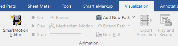
[1] Click [Add New Path], check [Custom], set the duration, and click [OK].
[2] Click [Extend Path] of pull-down menu in the [Visualization] tab.
[3] Select the pre-created path. The created path will be applied as the animation path.
Related Articles
Moving an Animation Path
When you want to add motion to a created model, you can drag and drop an item from the [Animation] section in the Catalog Browser onto a part to assign a specific movement. If you need to change the area where the movement occurs, you can adjust the ...Create cylinder link mechanism animation
First, you will set constraints in the link section of the cylinder. Thereby, you can operate the cylinder rod and operate the parts linked to the cylinder. [1] To operate the cylinder rod, make the rod and tip nut into one assembly, Separate them ...Hiding a Part During a Specific Interval of an Animation
The [Visualization] tab in IRONCAD includes animation functions that allow you to apply motion to parts. By setting up animations for a part, you can make it temporarily invisible during a specific interval of the animation. To toggle the visibility ...Create actions that the spring stretches
Explain how to create an animation of spring (spring) telescopic. This section explains how to create an animation of a spring (coil) extending and compressing. You can represent the spring’s motion by creating its shape using Sweep, and applying ...Set Insert Joint Point and create continuous pipes and mounts
This section explains how to use the [Attachment Point] function to build continuous pipe structures or equipment base frames in IRONCAD. In piping design and equipment base structures, it is common to use multiple sections of the same type of round ...