chamfering and fillet with sheet metal parts
Chamfering and filleting can be performed on sheet metal parts in the same way as on regular parts by selecting edges.
Previously, vertex fillets and vertex chamfers in the sheet metal catalog were applied using a drag-and-drop method. However, with the enhanced chamfer and fillet features, you now perform these operations by selecting edges.
The enhanced functionality allows you to apply chamfers and fillets to all corners of a sheet metal part at once.
Procedure:
[1] Click [Corner Break] in the [Sheet Metal] tab.
[2] Select Part
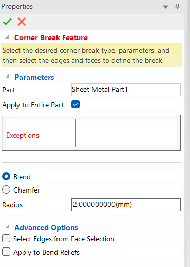
In case you check the [Apply to Entire Part].
Fillet application points are automatically detected.
In case you uncheck the [Apply to Entire Part].
You can select edges manually.
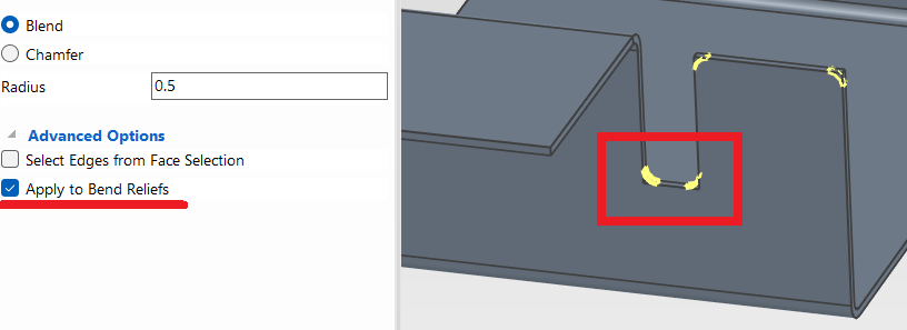
[3] Select Bend or Chamfer, then enter Radius or Distance.
Option:
[Select Edges from Face Selection] : Check this box when selecting the target edge with the surface.
[Apply to Bend Reliefs] : It is automatically detected if bend relief had been created.
Please refer to the video below.
IC-038
Related Articles
Create Sheet Metal Parts from Solid Parts
This section explains how to create sheet metal parts from solid parts either imported via intermediate files or created directly in IRONCAD. Shapes Convertible to Sheet Metal Parts Example: Shapes Convertible to Sheet Metal Parts. Both solid parts ...Create deployment parts from solid/surface
This section explains how to convert parts imported from intermediate files (without edit history) or parts created using the [Shape] catalog in IRONCAD into flattened parts. Flattened parts can be projected into CAXA Draft for drawing creation. Use ...Multiple parts into one part (Boolean - Union)
Explain how to make multiple parts into one part. Procedures: [1] Click [Boolean] on the [Feature] tab. [2] Select [Union] from the [Properties]. [3] Select multiple parts to change one part with left mouse click. The selected parts are added to the ...Add sketch cut lines to create sheet metal parts from solid parts
This section explains how to use lines drawn in a sketch as cut lines to create sheet metal parts from solid parts. By utilizing the lines drawn in the sketch, you can easily create sheet metal parts with cut lines along all four edges, as shown in ...Creating a Sheet Metal Part Using [Curved Stock]
This section explains how to create sheet metal using [Curved Stock]. Procedure: [1] Drag and drop [Curved Stock] from the [Sheet Metal] catalog. [2] In the [Select Stock] window, choose a stock and click [OK]. The visibility of this window can be ...