Add sketch cut lines to create sheet metal parts from solid parts
This section explains how to use lines drawn in a sketch as cut lines to create sheet metal parts from solid parts.
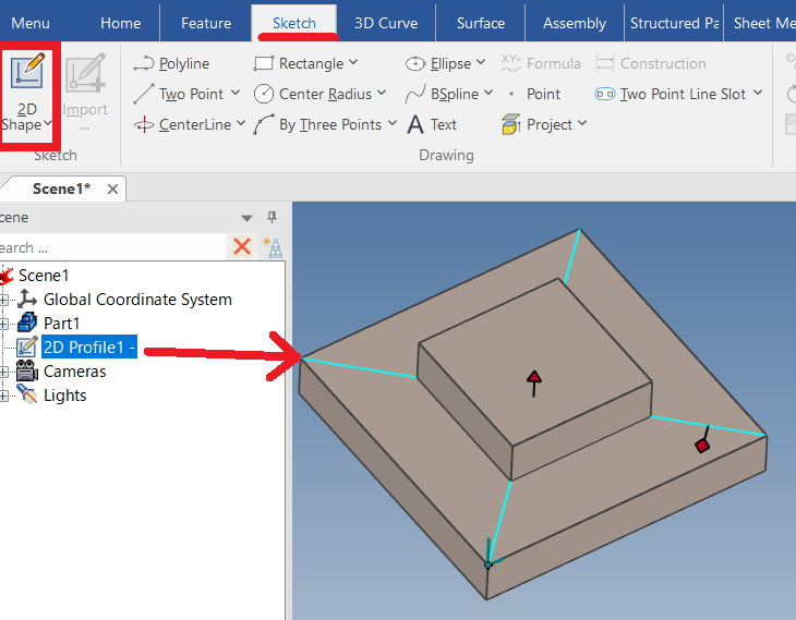
By utilizing the lines drawn in the sketch, you can easily create sheet metal parts with cut lines along all four edges, as shown in the example below.
↓
Procedure:
[1] Create solid model.
[2] Create a sketch line at the division point.
[3] Click [Solid part to Sheetmetal part] in the [Sheet Metal] tab.
[4] Configure the properties.
Face Selection: Select the face corresponding to the stock surface.
Bend Edges Selection: Select all the areas to be bent. ※ Bleu edges
Please refer to the video for the selection order.
Please refer to the video for the selection order.
Cut: Select the sketch created in [2].
[5] Click [OK].
Please refer to the video below.
IC-131
Related Articles
Create Sheet Metal Parts from Solid Parts
This section explains how to create sheet metal parts from solid parts either imported via intermediate files or created directly in IRONCAD. Shapes Convertible to Sheet Metal Parts Example: Shapes Convertible to Sheet Metal Parts. Both solid parts ...Create deployment parts from solid/surface
This section explains how to convert parts imported from intermediate files (without edit history) or parts created using the [Shape] catalog in IRONCAD into flattened parts. Flattened parts can be projected into CAXA Draft for drawing creation. Use ...Project some parts into 2D with imaginary lines
It changes line type of some In the 2D assembly drawing, in addition to the main design data, it want to may be expressed in line types (imagination lines) other than solid lines. Using the 3D Configuration function, it can project to be divided into ...Creating a Sheet Metal Part from a Solid Part (Hopper Example)
This section explains how to create a hopper-shaped sheet metal part from a solid part. Procedure: [1] Create the base shape of the hopper using a solid model. Do not include any fillets in the solid geometry. [2] Go to the [Sheet Metal] tab and ...Creating a Sheet Metal Part Using [Curved Stock]
This section explains how to create sheet metal using [Curved Stock]. Procedure: [1] Drag and drop [Curved Stock] from the [Sheet Metal] catalog. [2] In the [Select Stock] window, choose a stock and click [OK]. The visibility of this window can be ...