Create Progressive Dimensions (Coordinate Dimension)
In CAXA Draft, progressive dimension is referred to as [Coordinate Dimension].
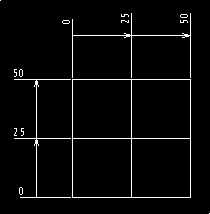
To create dimensions based on any arbitrary reference point in the drawing, use [Align] in the [Coordinate Dimensions].
When you select [Align], the instance menu will appear at the bottom left of the screen.
(Although the image is divided, in actual use, the menu is displayed in a horizontal line.)

Please configure the instance menu settings according to how you want the coordinate dimensions to appear.
Instance Menu Descriptions:
1. Sign / Positive Sign
Dimensions in the positive direction (right or upward from the reference) are positive (+), and those in the negative direction (left or downward) are negative (−).
- To include the minus (−) sign for negative dimensions, select [Sign].
- To omit the minus (−) sign, select [Positive Sign].
2. Draw arrow of the derivation point / Don't draw arrow of the derivation point
To display an arrow at the end of the dimension extension line (used to select the measurement reference point), select [Draw arrow of the derivation point].
To omit the arrow, select [Draw arrow of the derivation point].
Draw arrow of the derivation point
An arrow is shown at the end of the extension line.
An arrow is shown at the end of the extension line.
Don't arrow of the derivation point
No arrow is shown at the end of the extension line.
3. Dim line Opened / Dim line closed
To draw a dimension line between the extension lines, select [Dim line opened].
To omit the dimension line, select [Dim line closed].
To draw a dimension line between the extension lines, select [Dim line opened].
To omit the dimension line, select [Dim line closed].
Dim line opened
A dimension line is displayed between extension lines.
Dim line closed
No dimension line is displayed between extension lines.
4. Arrow Opened / Arrow Closed
To display arrows on the dimension line between extension lines, select [Arrow Opened].
To omit arrows, select [Arrow Closed].
To display arrows on the dimension line between extension lines, select [Arrow Opened].
To omit arrows, select [Arrow Closed].
Arrow Opened
Arrows are displayed on the dimension line.
Arrows are displayed on the dimension line.
Arrow closed
No arrows are displayed on the dimension line.
5. Draw origin / Don't draw origin
This setting determines whether to display a point at the initial reference (origin) point.
There is no visible difference in appearance.
Note that deleting the dimension will also delete the origin point.
Show Origin Point
Show Origin Point
A red circular point is created.
6. Aligned point extension
This sets the distance from the dimension line to the dimension value.
The value is displayed further from the current dimension line position by the specified amount.
Example:
If the extension length is set to [10], the dimension value appears 10 mm farther from the original dimension line (in yellow).
Since the dimension line moves toward the drawing, the gap between it and the drawing becomes narrower.
The initial reference dimension value should have a slightly larger space.

Once a dimension is created, this setting cannot be changed.
Make sure to set this in the instance menu before creating dimensions.
Make sure to set this in the instance menu before creating dimensions.
7. Prefix
Any symbols or characters entered as a prefix will appear before the dimension value.
8. Postfix
Any symbols or characters entered as a suffix will appear after the dimension value.
9. Basic Value
To manually override the measured dimension with a custom value, enter the desired number directly in this field.
The default [Calculated Value] shown is the measured value.
You can enter this value even during the dimensioning process.
The initial reference value is 0. To artificially change the second measured value, input the reference value before confirming the second dimension point.
Example:
If the measured value is 25 and you input a basic value of 10 before confirming the second dimension point:
Enter Basic Value [10]
The measured value is 25, but the displayed value will reflect the input basic value of 10.
The basic value must be set each time.
After applying it once, it reverts to the original measured value.
You can also enter non-numeric characters.
Arrow Settings:
The arrows for coordinate dimensions use the [Leader] arrow settings defined [Arrowheads] in the [Dimension] style.
If the arrow for [Leader] in the [Dimension] style is set to [None], arrows will not be displayed — even if you configure the instance menu with settings like [Draw arrow of the derivation point], [Dim line opened], or [Arrow Opened].
Related Articles
Create dimensions with the "Hole Dimension" command
Explain how to create dimensions with the "Hole Dimension" on the "3D Interface" tab. The Hole Dimension command displays dimensions on holes projected onto CAXA Draft based on hole information created with 3D data. Examples of projections linked to ...Creating Hole Coordinate Dimensions
This section explains how to create hole coordinate dimensions. [Hole] of coordinate dimensions display the X and Y coordinate values of holes in a projected view from an arbitrary reference point. You can also select points on shapes, not just ...Creating Free Coordinate Dimensions
This section explains how to create free coordinate dimensions. Define the starting point and fill in the coordinate dimensions while selecting the X and Y coordinates. You define a starting point and input coordinate dimension values by selecting X ...Create tape dimensions/curvature radius dimensions/large diameter circular dimensions/continuous angle dimensions
The CAXA Draft drawing explains how to create the following special dimensions: Pyramid/Pitch Curvature Dimension Big Arc Angle Continuous Please refer to the video below. CA-033Create dimensions in parallel for angled parts
Introduce how to create dimensions in parallel for an angled part. In case of "Base" command [1] Select "Base" from Smart Dimension pull-down menu on the "Annotation" tab. [2] Select a line from draw, then an endpoint (intersection) or line. By both ...