Create spin shapes (solid) at the edges and center lines of different parts
This section explains to create a spin shape using an edge or centerline from a different part as the axis of rotation.
Procedure:
[1] Select either the [Torus] or [Pie] shape in the [Shape] catalog.
[2] Use an edge or center axis from another part as the spin axis.
[3] Position and align the shape using [TriBall].
[4] Edit Cross-Section of the Torus.
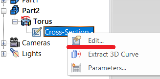
[5] Edit or delete the original cross-section, then create new sketch.
This method allows you to construct spin shapes based on references from other parts in your assembly.
Please refer to the video below.
IC-006
Related Articles
Create Sheet Metal Parts from Solid Parts
This section explains how to create sheet metal parts from solid parts either imported via intermediate files or created directly in IRONCAD. Shapes Convertible to Sheet Metal Parts Example: Shapes Convertible to Sheet Metal Parts. Both solid parts ...Create deployment parts from solid/surface
This section explains how to convert parts imported from intermediate files (without edit history) or parts created using the [Shape] catalog in IRONCAD into flattened parts. Flattened parts can be projected into CAXA Draft for drawing creation. Use ...Add sketch cut lines to create sheet metal parts from solid parts
This section explains how to use lines drawn in a sketch as cut lines to create sheet metal parts from solid parts. By utilizing the lines drawn in the sketch, you can easily create sheet metal parts with cut lines along all four edges, as shown in ...Project some parts into 2D with imaginary lines
It changes line type of some In the 2D assembly drawing, in addition to the main design data, it want to may be expressed in line types (imagination lines) other than solid lines. Using the 3D Configuration function, it can project to be divided into ...Create the center line of arc long holes
Since the center line of arc long holes is not created automatically, we will explain how to create it manually. "Center Line of Circle Array" command on the "Common" tab. Procedures: [1] Double-click the projection diagram, move to the block's place ...