Creating Piping with [Auto Route]
Starting with IRONCAD 2025, a new [Piping] tab has been added, providing piping creation functionality.
This section explains how to create piping from a flange using [Auto Route] under the [Piping] tab.
Procedure:
[1] Go to the [Piping] tab and click [Create Pipe].
[2] From the [ToolBox Browser], drag and drop a flange that complies with the available standards.

Currently, JIS standards are not available.
[3] In [Properties], set the flange size, then click [OK].
[4] Configure settings such as Pipe Size and Bending Method (Radius/Elbow).
After making the desired settings, select [OK].
[5] Use [Line] under the [Piping] tab to create a 3D Curve at the connection point.
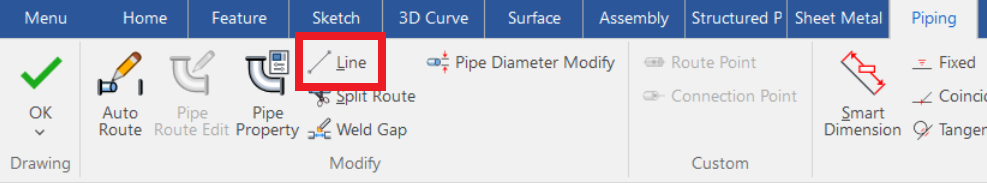

The 3D Curve serves as the path for the piping.
[6] Go to the [Piping] tab and click [Auto Route].
[7] Select two points on the 3D curve where the piping should connect.
[8] In [Route Tip], select the desired route, then execute with [OK].
Please refer to the video below.
IC-145
Related Articles
Create Piping
This section explains how to create piping and piping components using the [Piping] tab. Placing Flanges and Creating Piping IC-150 Inserting Tees IC-151 Inserting Elbows and Creating Piping IC-152 Inserting Crosses and Creating Piping IC-153Set Insert Joint Point and create continuous pipes and mounts
This section explains how to use the [Attachment Point] function to build continuous pipe structures or equipment base frames in IRONCAD. In piping design and equipment base structures, it is common to use multiple sections of the same type of round ...Creating Staggered Dimension
This section explains how to create [Staggered Dimension]. When dimension lines and text become crowded, you can place coordinate dimensions using leader lines with bends to specify their positions clearly. There are two methods for creating stepped ...Editing Centerlines After Creating a Broken View
This section explains how to edit centerlines after creating a broken view in CAXA Draft. Procedure: [1] Select the broken view, right-click, and click [View edit]. After creating a breakout view, you cannot edit the centerline by double-clicking the ...Creating Continuous 3D Curves Using TriBall
The following instructions are based on IRONCAD 2022. In IRONCAD 2021 and earlier versions, the command locations differ slightly, but the operation method is the same. When creating a continuous 3D curve passing through multiple specified points, ...