Add an angle to the dimension extension line
When entering dimensions for a figure in CAXA Draft, the dimension lines are usually created horizontally/vertically or parallel to the shape lines (left figure). This section explains how to add an angle the dimension extension lines. (right figure).
Procedures:
[1] Create the dimension. The dimension extension line is straight.
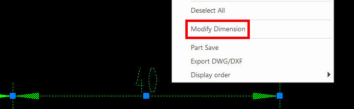
[2] Select the dimensions and right-click.
Click [Modify Dimension].
[3] In the status bar, change the value for item 4: [Extension Line Angle].
[4] Determine the position of the dimension.

If the projection view is tilted, use the figure’s lines or create separate guide lines as needed.
Please refer to the video below.
CA-012
Related Articles
Create tape dimensions/curvature radius dimensions/large diameter circular dimensions/continuous angle dimensions
The CAXA Draft drawing explains how to create the following special dimensions: Pyramid/Pitch Curvature Dimension Big Arc Angle Continuous Please refer to the video below. CA-033Change the length of the line by specifying the extension direction (IRONCAD/Setch Mode)
This section explains how to change the length of a line in a specified direction during a 3D sketch in IRONCAD. Procedure: [1] In the sketching screen, use [Polyline] to draw a horizontal straight line. [2] Create dimensions using [SmartDimension]. ...Create a fan model
Fan-shaped models can be created in the Spin Wizard or Extrusion Wizard. In case of Spin Wizard [1] Click "Spin Wizard" on the Feature tab. [2] Select Plane Type, then draw sketch. Create a sketch with the Y axis pointing upward. Then click "Finish" ...Change Chamfer Dimension Notation
This section explains how to work with chamfer dimensions in CAXA Draft. When adding chamfer dimensions in CAXA Draft, you can choose from the following four notation formats: Dimensions × Dimensions (1×1) Dimensions x Angle (1×45°) Angle × Dimension ...Create Progressive Dimensions (Coordinate Dimension)
In CAXA Draft, progressive dimension is referred to as [Coordinate Dimension]. To create dimensions based on any arbitrary reference point in the drawing, use [Align] in the [Coordinate Dimensions]. When you select [Align], the instance menu will ...