Change Chamfer Dimension Notation
This section explains how to work with chamfer dimensions in CAXA Draft.
When adding chamfer dimensions in CAXA Draft, you can choose from the following four notation formats:
- Dimensions × Dimensions (1×1)
- Dimensions x Angle (1×45°)
- Angle × Dimension (45°×1)
- Prefix with symbol C before the dimension (C1)
To add chamfer dimensions as shown in the diagram below, follow the steps below:
Procedure:
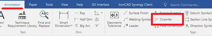
[1] Click [Chamfer] in the [Annotation] tab.
[2] In the instance menu at the bottom left, set item [3.] to [Perp chamfer-line].
[3] Set item [4.] to [Horizon Text].
[4] Set item [5.] to [C1].
[5] Select the line segment where you want to place the chamfer dimension.
The chamfer dimension will be inserted accordingly.
Related Articles
Split the face (solid/surface)
This section explains how to split specific faces of a solid or surface using arbitrary 3D curves. Use the [Split Faces] command located in the [Features] tab. There are four types of face splitting methods: Projection Projects a sketch, edge, or 3D ...Change some of the bend angles created with sketch bends
This section explains how to modify the bend angles of sheet metal parts created using the [Create Sketch Bend] feature. While the [Set Bend Angle] command allows you to set the bend angle for each bend line at the time of creating the sketch bend, ...Creating a Half Dimension
This section explains how to create a half dimension. The value displayed in a half dimension is calculated as the distance between two specified points × 2. Procedure: [1] Click [Half Dim] in the [Annotation] tab. [2] First, select a midpoint or ...Change the Frame Type of Part Numbers
This section explains how to change the shape of part numbers. Part number shapes are configured in the Bill of Materials (BOM) input screen. Procedure: [1] After projecting the drawing, click [Import 3D BOM] in the [3D Interface] tab. Since part ...Create Progressive Dimensions (Coordinate Dimension)
In CAXA Draft, progressive dimension is referred to as [Coordinate Dimension]. To create dimensions based on any arbitrary reference point in the drawing, use [Align] in the [Coordinate Dimensions]. When you select [Align], the instance menu will ...