Create chamfering dimensions for tilted parts
Explain how to create chamfer dimensions (C style) of tilted parts.
Auxiliary View can be created in the same way.
Procedure:
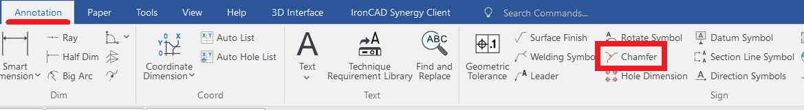
[1] Click "Chamfer" on the Annotation tab.
[2] Set the instance menu items at the bottom left of the screen.
1: Default Style
2: Select Axis
3: perp chamfer-line
4: (Optional)
5: C1

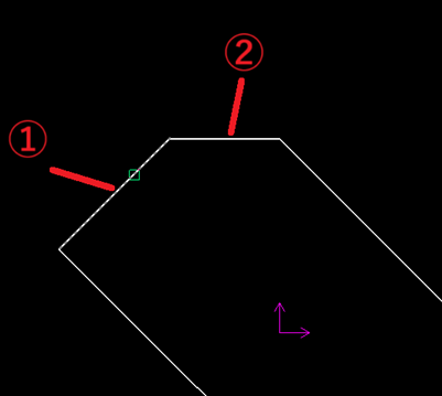
[3] Specify the line
①Axis.
①Axis.
②C side
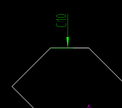
[4] Place the chamfer dimension.
Please refer to the video below.
CA-008
Related Articles
Create dimensions in parallel for angled parts
Introduce how to create dimensions in parallel for an angled part. In case of "Base" command [1] Select "Base" from Smart Dimension pull-down menu on the "Annotation" tab. [2] Select a line from draw, then an endpoint (intersection) or line. By both ...Multiple parts into one part (Boolean - Union)
Explain how to make multiple parts into one part. Procedures: [1] Click [Boolean] on the [Feature] tab. [2] Select [Union] from the [Properties]. [3] Select multiple parts to change one part with left mouse click. The selected parts are added to the ...Create dimensions with the "Hole Dimension" command
Explain how to create dimensions with the "Hole Dimension" on the "3D Interface" tab. The Hole Dimension command displays dimensions on holes projected onto CAXA Draft based on hole information created with 3D data. Examples of projections linked to ...Create Progressive Dimensions (Coordinate Dimension)
In CAXA Draft, progressive dimension is referred to as [Coordinate Dimension]. To create dimensions based on any arbitrary reference point in the drawing, use [Align] in the [Coordinate Dimensions]. When you select [Align], the instance menu will ...Create tape dimensions/curvature radius dimensions/large diameter circular dimensions/continuous angle dimensions
The CAXA Draft drawing explains how to create the following special dimensions: Pyramid/Pitch Curvature Dimension Big Arc Angle Continuous Please refer to the video below. CA-033