Binding parts in the assembly with SmartDimension
This section explains how to constrain a part within an assembly using Smart Dimension so that it follows another part.
Procedure:
[1] Create dimension between the assembly and the other part.
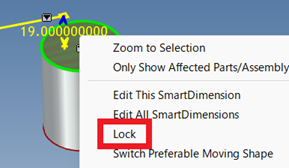
[2] Right-click on the dimension and enable [Lock] from the menu.
[3] Select the SmartDimension, then click the small downward triangle icon.
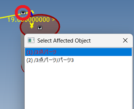
[4] Select the part within the assembly as the driven object.
Please refer to the video below.
IC-090
If you want the currently selected object to be set as the affected/owning object by default when creating a dimension, follow the steps below:
[1] Open [Options] in the [Menu].
[2] In the list on the left, select [Interaction], then scroll down to [3D Smart Dimension/Constraint].
[3] Check [Keep selected shape as affected/owning object when creating dimension].
[4] After checking the box, click [Apply] and then [OK].
Related Articles
Project some parts into 2D with imaginary lines
It changes line type of some In the 2D assembly drawing, in addition to the main design data, it want to may be expressed in line types (imagination lines) other than solid lines. Using the 3D Configuration function, it can project to be divided into ...Extend Parts/Assembly
This section explains how to extend parts or assemblies in bulk. Procedure: [1] Select the part(s) or assembly(assemblies) to be extended. [2] Go to the [Features] tab and select [Stretch Part/Assembly]. The [Extend Part/Assembly] function cannot be ...Set Parts as Active
When setting a part as active means currently modeled part only editable. This prevents accidental modifications to other parts. How to: Select the part you want to activate, then right-click and choose [Set as active] from the context menu. The name ...Check the cross section of parts/assembly
This section explains how to use the Part/Assembly Section tool to create section views of parts or assemblies. Procedure: [1] Select the part or assembly you want to section. [2] Click [Section Part/Assembly] in the [Tools] tab. The selected ...Hiding a Part During a Specific Interval of an Animation
The [Visualization] tab in IRONCAD includes animation functions that allow you to apply motion to parts. By setting up animations for a part, you can make it temporarily invisible during a specific interval of the animation. To toggle the visibility ...