Using the [Gear] Constraint to Rotate Gears
New Feature in IRONCAD 2024
A new [Gear] constraint has been added to the placement constraints.
This section explains how to simulate gear rotation using this feature.
Procedure:
[1] Position the two gear parts using the TriBall tool.
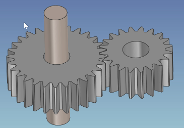
 The gears must be manually positioned.
[2] Fix the shafts using [Fixed in Parent],
Apply constraints between each gear and its corresponding shaft.
[3] Apply the [Gear] constraint between the two gears.
Please refer to the video below.
IC-127
Related Articles
Create a Cam Belts
This section explains the basic operations of [Cam Belt] in the [Flex Shapes] catalog. Procedure: Expand [Cam Belt] in the Scene Browser. Change size You can change the size of the cam belt by moving the negative feature cylinder (H Cylinder) using ...Creating Motion with Pin/Slot Constraint
This section explains an example of how to create motion using the Pin/Slot constraint. The Pin/Slot constraint is used when a pin must move along an elongated hole (slot) or groove. In this example, we will demonstrate how to set up a pin on a fixed ...Create an automatic list
This section explains how to create an [Auto list] as shown in the figure below, using CAXA Draft. Procedure: [1] Click [Create User Coordinate] in the [View] tab. Then you create coordinate system. [2] Click [Auto List] in the [Annotation] tab. [3] ...Create Movement Using [Walk] Feature
This section explains how to create a movement that simulates walk a building from the camera's point of view. Two cameras are required: the main camera and a viewpoint camera (walkthrough camera). When executing the animation, make sure the ...Creating a Bolt Hole Using [Custom Hole]
This section explains how to create a bolt hole using the [Custom Hole] feature found in the [Feature] tab. Procedure: [1] Go to the [Feature] tab and click [Custom Hole]. [2] Select the target part and click on the desired placement point. [3] In ...