Create Dimensions with Leader Lines
When adding dimensions to a projected view, dimensions may sometimes overlap with adjacent ones.
You can improve drawing readability by adding leader lines to the dimensions.
Procedure:
[1] Select the dimension, then click [Modify Dimension] in the [Annotation] tab.
[2] Instance menu appears at the bottom of the screen.
[3] From item 1, select [Text Position], and from item 2, select [Leader].
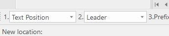
[4] Specify the new position for the dimension.

Arrows between adjacent dimensions can be made easier to read by changing them to solid dots (●) or none.

For vertical dimensions, it is not possible to rotate the dimension text vertically. Please keep this limitation in mind.
Please refer to the video below.
CA-024
Related Articles
Create Progressive Dimensions (Coordinate Dimension)
In CAXA Draft, progressive dimension is referred to as [Coordinate Dimension]. To create dimensions based on any arbitrary reference point in the drawing, use [Align] in the [Coordinate Dimensions]. When you select [Align], the instance menu will ...Create dimensions in parallel for angled parts
Introduce how to create dimensions in parallel for an angled part. In case of "Base" command [1] Select "Base" from Smart Dimension pull-down menu on the "Annotation" tab. [2] Select a line from draw, then an endpoint (intersection) or line. By both ...Create dimensions with the "Hole Dimension" command
Explain how to create dimensions with the "Hole Dimension" on the "3D Interface" tab. The Hole Dimension command displays dimensions on holes projected onto CAXA Draft based on hole information created with 3D data. Examples of projections linked to ...Create tape dimensions/curvature radius dimensions/large diameter circular dimensions/continuous angle dimensions
The CAXA Draft drawing explains how to create the following special dimensions: Pyramid/Pitch Curvature Dimension Big Arc Angle Continuous Please refer to the video below. CA-033Create continuous angle dimensions
This section explains how to create [Angle Continuous] dimensions. As shown in the figure below, you can create dimensions for a series of continuous angles in a single operation on a plan view or similar drawing. Please refer to the video below. ...