Creat a Helical Groove on a Cylinder
This section explains how to create a helical groove on the side of a cylinder using the [Helix] option under 3D Curve.
The helical groove is created using a combination of the [Helix] command from 3D Curve and the [Sweep] command.
Procedure:
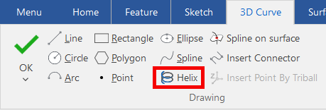
[1] Click the [Helix] in the [3D Curve] tab and create a helix (path) along the side of the cylinder.
[2] Create a sketch of the groove perpendicular to the helix.
When creating the groove sketch, select the end point of the helix (path); a 2D sketch grid will automatically be placed perpendicular to the helix (path).
The sketch for the groove is created using [2D Shape] in the [Sketch] tab.
[3] Use the helix (path) and the cross-sectional sketch of the groove with the [Sweep] command to cut along the side of the cylinder.
Please refer to the video below.
To Change the Rotation Direction of the Helix (Path) (※1)
You can switch between right-handed and left-handed rotation by checking the [Reversed Helix Direction] option in the properties of the helix settings screen.
※1 Changing the Rotation Direction of the Helix (Path)
If you want to change the rotation direction of the helix (path) after creating the cross-sectional sketch or the helical groove itself, you will need to delete the existing cross-sectional sketch, adjust for the new rotation direction, and recreate the sketch.
Then, recreate the helix (path) and perform the [Sweep] again.
Then, recreate the helix (path) and perform the [Sweep] again.

Make sure to change the rotation direction before creating the cross-sectional sketch of the groove.
If you change the direction after the sketch or the groove has been created, the cross-sectional sketch will remain in its original orientation (position), causing a mismatch with the new helix direction. This will distort the shape of the helical groove.
If you change the direction after the sketch or the groove has been created, the cross-sectional sketch will remain in its original orientation (position), causing a mismatch with the new helix direction. This will distort the shape of the helical groove.
Related Articles
Creating a Groove on a Cylindrical Surface Using Sweep
This section explains how to create a groove for a cam on a cylindrical shape. The groove is created in a direction perpendicular to the center axis of the cylinder. Procedure: [1] Draw a 2D sketch to use as a guide curve for the cylindrical surface. ...Create cylinder link mechanism animation
First, you will set constraints in the link section of the cylinder. Thereby, you can operate the cylinder rod and operate the parts linked to the cylinder. [1] To operate the cylinder rod, make the rod and tip nut into one assembly, Separate them ...Creating Grooves on a Cylindrical Surface Using Wrap Emboss
This section explains how to create evenly spaced radial grooves on the side surface of a cylindrical shape. Procedure: [1] Check the circumference length of the cylinder. [2] Go to the [Sketch] tab and create sketch line that match the circumference ...Create a round bar with a 3D curve (create a curved round bar)
After creating lines with "3D Curve", it will explain how to create a round stick with "Sweep". The following actions are based on IRONCAD 2022 and later versions: Prior to IRONCAD 2021, the command placement is different, but the operation method is ...Set the tape on the cylinder
This section explains how to create a tapered pin by applying a draft angle to the [Cylinder] in the [Shape] Catalog. Procedure: [1] Drag & drop [Cylinder] from the [Shape] catalog. [2] Click [Draft Faces] in the [Feature] tab. [3] Select [Neutral ...