Creating a Groove on a Cylindrical Surface Using Sweep
This section explains how to create a groove for a cam on a cylindrical shape.
The groove is created in a direction perpendicular to the center axis of the cylinder.
Procedure:
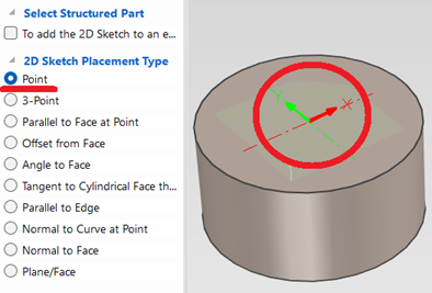
[1] Draw a 2D sketch to use as a guide curve for the cylindrical surface.
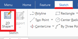
Click [2D Shape] in the [Sketch] tab.
Select "Point" and click center point of cylinder. Then Click [OK].
[2] Go to the [Features] tab and click [Wrap Curve].
Select "Point" and click center point of cylinder. Then Click [OK].
[2] Go to the [Features] tab and click [Wrap Curve].
[3] Create a cross-sectional shape of the groove.
[4] Select the guide curve and the profile created in Steps [1] and [3,] and configure the sweep properties.
[5] Click [OK].
 If an error occurs, try changing the modeling kernel to [Parasolid] and check again.
Please refer to the video below.
IC-124
Related Articles
Creating Grooves on a Cylindrical Surface Using Wrap Emboss
This section explains how to create evenly spaced radial grooves on the side surface of a cylindrical shape. Procedure: [1] Check the circumference length of the cylinder. [2] Go to the [Sketch] tab and create sketch line that match the circumference ...Creat a Helical Groove on a Cylinder
This section explains how to create a helical groove on the side of a cylinder using the [Helix] option under 3D Curve. The helical groove is created using a combination of the [Helix] command from 3D Curve and the [Sweep] command. Procedure: [1] ...Creating a Surface Texture Symbol
This section explains how to create a surface texture symbol in a drawing using CAXA Draft. The surface texture symbol is used to indicate surface roughness, typically on reference planes or mounting surfaces such as brackets. CAXA Draft supports ...Create a Cam Belts
This section explains the basic operations of [Cam Belt] in the [Flex Shapes] catalog. Procedure: Expand [Cam Belt] in the Scene Browser. Change size You can change the size of the cam belt by moving the negative feature cylinder (H Cylinder) using ...Alie cylindrical parts with concentric restraint
This section explains how to position cylindrical parts and cylindrical holes with different orientations using concentric alignment. Methods: Using TriBall to manually align parts concentrically → No constraint applied Using the [Concentric] ...