Create a connection hose
This section explains how to create a hose that connects fixed-position pipes.
[1] Click [3D Curve] in the [3D Curve] tab.
[2] Click [Spline].
n the [3D Curve] group.
[3] Specify each center points to create a 3D curve.
[4] After creating the 3D curve, select it. Direction arrows will appear at the connection points.
Hover your mouse over the arrow, right-click, and select [Perpendicular to Face] from the menu.
[5] Repeat the same process on the opposite end to make that connection perpendicular as well.
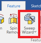
[6] select [Sweep Wizard] in the [Feature] tab, then choose the 3D curve you created.
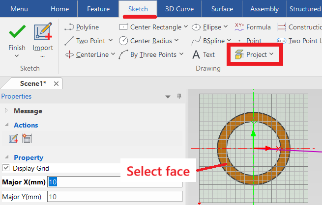
[7] In 2D Sketch mode, draw the cross-sectional profile of the hose.
Click [Project] in the [Draw] group, then project the hose diameter from the pipe geometry.
Use the Offset command if needed to adjust the diameter.
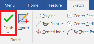
[8] Click [Finish] of 2D Sketch, and the sweep shape will be generated.
Note: An error may occur at this stage.
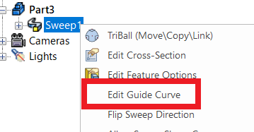
[9] If an error occurs, edit the sweep path to adjust it.
In the Scene Browser, right-click on [Sweep], and click [Edit Guide Curve].
You can drag the intermediate points or move them using the TriBall.
After editing, click [OK] to regenerate the sweep shape.
Depending on the situation, changing the modeling kernel for the hose part may help avoid errors.
While using ACIS may result in slower performance, it is recommended to use Parasolid whenever possible.
Please refer to the video below.
IC-037
Related Articles
Set Insert Joint Point and create continuous pipes and mounts
This section explains how to use the [Attachment Point] function to build continuous pipe structures or equipment base frames in IRONCAD. In piping design and equipment base structures, it is common to use multiple sections of the same type of round ...Creating a Block (CAXA Draft)
This section explains how to create Block parts in CAXA Draft. Block parts allow you to register frequently used lines or shapes as blocks so that they can be easily inserted into drawings. By registering items such as bolts, pins, and annotations as ...Create Piping
This section explains how to create piping and piping components using the [Piping] tab. Placing Flanges and Creating Piping IC-150 Inserting Tees IC-151 Inserting Elbows and Creating Piping IC-152 Inserting Crosses and Creating Piping IC-153Create an automatic list
This section explains how to create an [Auto list] as shown in the figure below, using CAXA Draft. Procedure: [1] Click [Create User Coordinate] in the [View] tab. Then you create coordinate system. [2] Click [Auto List] in the [Annotation] tab. [3] ...Create annotations on drawings
In 2D drawings, notes are used to provide supplementary information for manufactured parts that may be difficult for others to interpret based solely on the drawing, dimensions, or symbols. This section explains how to create drawing notes in CAXA ...