Set Parts as Active
When setting a part as active means currently modeled part only editable. This prevents accidental modifications to other parts.
How to:
Select the part you want to activate, then right-click and choose [Set as active] from the context menu.
The name of the active part will be displayed in blue in the Scene Browser.
The blue color is light, so please check carefully.
How to deactivate
To deactivate, select any part in the Scene Browser, right-click, and choose [Deactivate All].
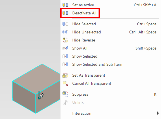
You can perform the "Deactivate All" operation from any part, not just the currently active one.
Optional Settings:
When a specific part is set as active, you can make all other non-active parts appear semi-transparent.
[1] Open [Option] of 3D Scene.
[2] Go to [Interaction], then check [Don't display other shapes transparently when editing features of the current shape] in the [Feature Behavior].
- Check: Non-active parts will be displayed normally (not transparent). (This is the default in IRONCAD 2023)
- Uncheck: Non-active parts will be displayed as semi-transparent.
Example when unchecked: The left part is active, and the right part is inactive.

Pressing the shortcut key [Ctrl + Shift + A] will set the selected part as active.
If you use the shortcut, be careful—it's easy to unintentionally continue working without noticing the part has been activated.
If you activate a part by mistake, press [Ctrl + Shift + A] again on the active part or follow the steps in How to Deactivate to correct it.
If you use the shortcut, be careful—it's easy to unintentionally continue working without noticing the part has been activated.
If you activate a part by mistake, press [Ctrl + Shift + A] again on the active part or follow the steps in How to Deactivate to correct it.
Related Articles
Multiple parts into one part (Boolean - Union)
Explain how to make multiple parts into one part. Procedures: [1] Click [Boolean] on the [Feature] tab. [2] Select [Union] from the [Properties]. [3] Select multiple parts to change one part with left mouse click. The selected parts are added to the ...Hiding a Part During a Specific Interval of an Animation
The [Visualization] tab in IRONCAD includes animation functions that allow you to apply motion to parts. By setting up animations for a part, you can make it temporarily invisible during a specific interval of the animation. To toggle the visibility ...Create deployment parts from solid/surface
This section explains how to convert parts imported from intermediate files (without edit history) or parts created using the [Shape] catalog in IRONCAD into flattened parts. Flattened parts can be projected into CAXA Draft for drawing creation. Use ...Edit Brep parts
When you obtain 3D data for purchased components from other 3D model download services, you can import them into IRONCAD using compatible file extensions. For solid parts, you can perform direct editing and modifications using IRONCAD’s Direct ...Project some parts into 2D with imaginary lines
It changes line type of some In the 2D assembly drawing, in addition to the main design data, it want to may be expressed in line types (imagination lines) other than solid lines. Using the 3D Configuration function, it can project to be divided into ...