Use Design Valuations
This section explains how to use [DesignVariations].
With Design Variations, you can create and manage multiple design options by utilizing parameters assigned to shapes, parts, or assemblies. You can then switch between these variations as needed.
Procedure:
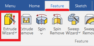
[1] Click [Extrude Wizard] in the [Features] tab to create a part.
Create sketch. When creating a cross-sectional shape, use [SmartDimension].
After creating a cross-sectional shape first, there is no problem if you create a part with Extrusion.
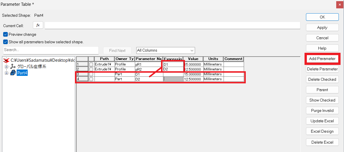
[2] Select the shape/parts and set the [Parameters...].
Create parameters for the dimensions you want to change. ※Please refer to the video.
[3] With the shape/part selected, go to the [Add-Ins] tab → [DesignVariations], and choose [Add Design Variation].
If DesignVariations is not visible, go to [Add-Ins] tab → [General] group → click [Add-In Applications...],
then in the Application/Add-Ins dialog box, check [DesignVariations] and click [OK] to enable it.
[4] After clicking [Add Design Variation], then select [Edit Design Variation].
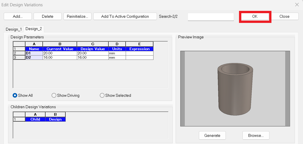
[5] The Edit Design Variations dialog box will appear.
Set the [Design Value] of the Parameters.
[6] Click [Add] to create a new design variation (tab).
Set the Design Values for the new variation.
[7] Generate a preview for the selected design variation.
[8] Apply the selected variation.
[9] Click [OK].
Please refer to the video below.
IC-093
Related Articles
Link Design Variations and Configurations
Explain how to link the display status of the part that created the design variation and the Configuration. Design Variations: One part can set different states of length and diameter and change shape. Configuration: You can toggle the display status ...Display the candidate for the next command to use
You can automatically display candidates for the next command to use, depending on the object selection. (Quick Access Command) The menu is displayed near the mouse cursor, so you can smoothly migrate to the next operation. You can also customize it, ...Use virtual intersections when creating dimensions
This section explains how to create from virtual intersect point when creating dimensions. Procedure: [1] Click [Smart Dimension] in the [Annotation] tab. [2] Before specifying a point, press the [Space] key. Alternatively, hold down the [Shift] key ...Edit data without history
When displaying data created with other CAD software in IRONCAD, use intermediary file formats such as STEP or x_t to exchange the data. In IRONCAD, import the data using the [Import Geometry] command. The imported data will appear as a single solid ...Set Insert Joint Point and create continuous pipes and mounts
This section explains how to use the [Attachment Point] function to build continuous pipe structures or equipment base frames in IRONCAD. In piping design and equipment base structures, it is common to use multiple sections of the same type of round ...