Check the cross section of parts/assembly
This section explains how to use the Part/Assembly Section tool to create section views of parts or assemblies.
Procedure:
[1] Select the part or assembly you want to section.
[2] Click [Section Part/Assembly] in the [Tools] tab.
The selected part/assembly will be highlighted in white, and the Command Browser will appear.
[3] In [Section Settings] of [Create Section] browser, select the cutting plane type from the [Section Tool Type] dropdown menu.
The [Block] cutting tool uses a translucent block.
Other tools use a translucent plane, each with a different orientation.
[4] In [Section Options], click the [Define Section Tool] icon.
[5] Click a snap point (such as a point, face, or edge) on the object to place the cutting tool.
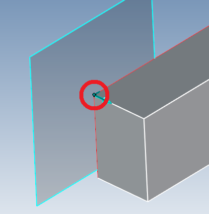
[6] Click [Reverse Surface Orientation] icon to change the cutting direction.
[7] Activate TriBall on the cutting tool to move it to the desired position.
Rotating the tool allows you to create angled section views.
[8] Click [✓] to create the section.
[9] After the section is created, you can select the [Section Tool] from the Scene Browser and you can move it using the TriBall.
Adding or Removing Parts/Assemblies from the Section Target
[1] To add or remove parts after the section tool is created, right-click the Section Tool and select [Add/Remove Parts] from the menu.
[2] In the Scene Browser, (①) select [Scene] and hold the Ctrl key to select parts to include or exclude.
Switch to the (②) [Edit Section] tab to activate the (③) [Section Options] commands.
Select [Add Parts] or [Exclude Parts], then (④) click the green check icon to complete the command.
Suppressing the Section Tool
You can temporarily disable a section by suppressing the section tool, allowing you to reuse it later.
Procedure:
[1] In the Scene Browser, select the [Section Tool].
[2] Right-click and select [Suppress] from the context menu.
※To reactivate the section, follow the same steps and select [Unsuppress].
[Precise Mode]
You can set the Section Tool to [Precise Mode] by right-clicking it in the Scene Browser.
Enabling Precision Mode allows you to measure the sectioned area and project the section geometry into CAXA Draft (2D drafting).
Please refer to the video below.
IC-094
Related Articles
Project some parts into 2D with imaginary lines
It changes line type of some In the 2D assembly drawing, in addition to the main design data, it want to may be expressed in line types (imagination lines) other than solid lines. Using the 3D Configuration function, it can project to be divided into ...Set Parts as Active
When setting a part as active means currently modeled part only editable. This prevents accidental modifications to other parts. How to: Select the part you want to activate, then right-click and choose [Set as active] from the context menu. The name ...Extend Parts/Assembly
This section explains how to extend parts or assemblies in bulk. Procedure: [1] Select the part(s) or assembly(assemblies) to be extended. [2] Go to the [Features] tab and select [Stretch Part/Assembly]. The [Extend Part/Assembly] function cannot be ...Create deployment parts from solid/surface
This section explains how to convert parts imported from intermediate files (without edit history) or parts created using the [Shape] catalog in IRONCAD into flattened parts. Flattened parts can be projected into CAXA Draft for drawing creation. Use ...Manually change the symbol of the cross-sectional label
In CAXA Draft, you can create section views from projection views linked to 3D models. When a section view is created, a "label" is automatically assigned. By default, the label uses alphabetical letters in sequence (A, B, C, ...). However, if a ...