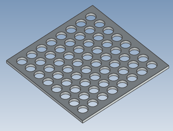
Create the same hole and shape on one side with a fill array
This section explains how to create features such as holes or blocks placed on a part surface, replicated at specified intervals across Use the [Pattern Feature] option under:
[Feature] tab → [Transform] group → [Pattern Feature] command. Select [Fill Pattern] from the pattern types.
This function allows you to create an array of shapes on the surface of a part with a specified spacing.
Example:
(illustration or description assumed here)
(illustration or description assumed here)
Procedure:
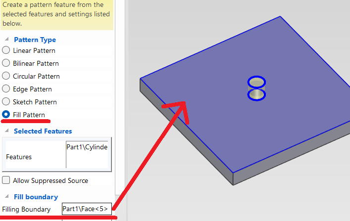
[1] Select Intellishape. (hole, Cylinder etc)
[2] Click [Pattern Feature].
[3] In the [Properties] select [Fill pattern], then click surface for [Filling Boundary].
[5] Select edge in the model for [Axis1] and enter [Offset 1].
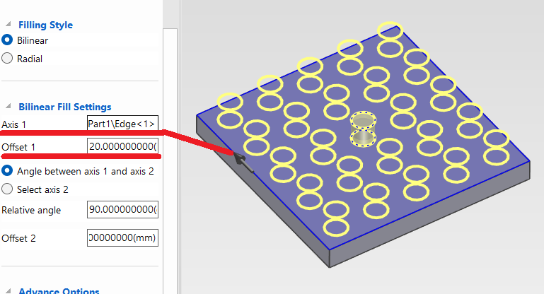
[6] Pattern shapes are created.
 The fill area is limited to the surface where the hole or block feature is placed.
For non-rectangular polygons such as pentagons or hexagons, the pattern is aligned and filled according to the specified edge.
The number of filled features is automatically calculated based on the size of the hole or block, and cannot be manually specified.
Please refer to the video below.
IC-054
Related Articles
Creating a Bolt Hole Using [Custom Hole]
This section explains how to create a bolt hole using the [Custom Hole] feature found in the [Feature] tab. Procedure: [1] Go to the [Feature] tab and click [Custom Hole]. [2] Select the target part and click on the desired placement point. [3] In ...Create dimensions with the "Hole Dimension" command
Explain how to create dimensions with the "Hole Dimension" on the "3D Interface" tab. The Hole Dimension command displays dimensions on holes projected onto CAXA Draft based on hole information created with 3D data. Examples of projections linked to ...Create tapered screws with pie holes and schematic screw mountains
This section explains how to create a tapered internal thread. IRONCAD is a CAD system that allows efficient modeling by utilizing items from the standard catalog. Tapered internal threads can also be easily created by using [Cut Pie] from the ...Move the position of the 2D shape drawn by sketching
When creating 3D shapes, you may need to create 2D sketch geometry. Sketch shapes can be drawn freely, and there may be cases where you move the drawn geometry. There are three methods for moving sketch geometry, as described below: Select the sketch ...Follow the hole and place the bolts - Assembly Array -
This section explains how to place bolts parallel to the edges of a shape. By using this feature, when the base plate shape changes but the bolt pitch remains the same, you can minimize the need to manually reposition the bolts. [1] Click [Assembly ...