Creating Display Configurations with Different Shapes by Linking Parameters to Excel
This section explains how to register the parameter names of 3D data with defined parameters in Excel and create multiple display configurations.
Procedure:
[1] Open [Parameters].
[2] Under [Add Parameter], create the necessary parameter items.
[3] Click [Excel Design].
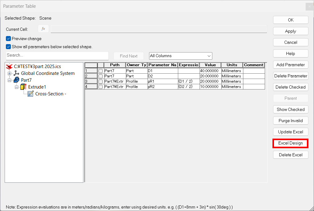
[4] From the IRONCAD parameter table, click the parameter names you have created.

They will be automatically added to Excel.
[5] In the Excel sheet, starting from cell "A7", enter the display configuration names and their corresponding values.
[6] Save the Excel file and check the display configurations at the bottom right of the IRONCAD screen.
Example: The created configurations Diameter 1 and Diameter 2 will be added to the display configurations.
Please refer to the video below.
IC-130
Related Articles
Link Design Variations and Configurations
Explain how to link the display status of the part that created the design variation and the Configuration. Design Variations: One part can set different states of length and diameter and change shape. Configuration: You can toggle the display status ...Change some of the bend angles created with sketch bends
This section explains how to modify the bend angles of sheet metal parts created using the [Create Sketch Bend] feature. While the [Set Bend Angle] command allows you to set the bend angle for each bend line at the time of creating the sketch bend, ...Change the Frame Type of Part Numbers
This section explains how to change the shape of part numbers. Part number shapes are configured in the Bill of Materials (BOM) input screen. Procedure: [1] After projecting the drawing, click [Import 3D BOM] in the [3D Interface] tab. Since part ...Display the candidate for the next command to use
You can automatically display candidates for the next command to use, depending on the object selection. (Quick Access Command) The menu is displayed near the mouse cursor, so you can smoothly migrate to the next operation. You can also customize it, ...Batch Change the Display Resolution of Multiple Elements (Surface Smoothness)
This section explains how to change the display resolution of elements in a 3D scene. All the examples shown below use the [Cylinder] from the [Shapes] catalog. As you move to the right, the cylinders appear more roughed. This is due to differences ...