Split bead parts (Brep)
This section explains how to split a Brep part using the [Split] function under the Feature tab.
Use [Split] command in the [Feature] tab.
This function can be used to extract components such as screws from Brep parts.
Procedure:
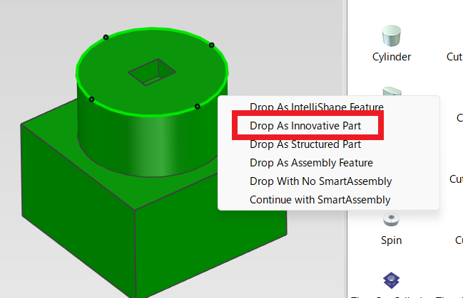
[1] From the catalog, place a [Cylinder] or similar part as a part to enclose the element of the Brep part you want to extract.
You can drag and drop using the right mouse button to display options and select a command from the menu.
[2] Adjust the length and size of the placed part as needed.
[3] Click [Split] in the [Feature] tab.
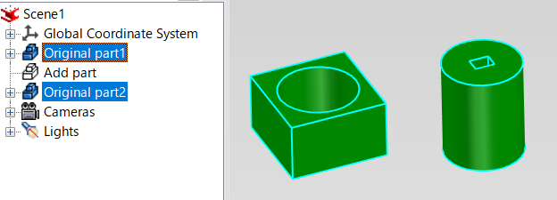
[4] Specify the Brep part as the [Target Part].
Specify the add part as the [Tool Part].
[5] Run the split command.
[6] Delete the split tool part if it is no longer needed.
Please rename each split parts.
Please refer to the video below.
IC-041
Related Articles
Split the face (solid/surface)
This section explains how to split specific faces of a solid or surface using arbitrary 3D curves. Use the [Split Faces] command located in the [Features] tab. There are four types of face splitting methods: Projection Projects a sketch, edge, or 3D ...Edit Brep parts
When you obtain 3D data for purchased components from other 3D model download services, you can import them into IRONCAD using compatible file extensions. For solid parts, you can perform direct editing and modifications using IRONCAD’s Direct ...Set Parts as Active
When setting a part as active means currently modeled part only editable. This prevents accidental modifications to other parts. How to: Select the part you want to activate, then right-click and choose [Set as active] from the context menu. The name ...Create deployment parts from solid/surface
This section explains how to convert parts imported from intermediate files (without edit history) or parts created using the [Shape] catalog in IRONCAD into flattened parts. Flattened parts can be projected into CAXA Draft for drawing creation. Use ...Project some parts into 2D with imaginary lines
It changes line type of some In the 2D assembly drawing, in addition to the main design data, it want to may be expressed in line types (imagination lines) other than solid lines. Using the 3D Configuration function, it can project to be divided into ...